Articles by "basic-idea"

 How to rewind armature of drill machine

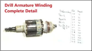
In this project we learn how to rewind armatore of drill machine. its very easy and simple process. 
1st we need some basic information about armature of drill machine.
Its duplex winding. 
How to rewind armature of drill machine

Pole is 2 north and south.
Segment is 24 
And slot is 12. 
We know pitch is equal to slot over pole.
12/2 =  Answer is 6
Mean we wind in 1 and 6 slot reshow 
For more simplify we make a simple chart of slot and segment combination.
Slot Segment
1-6 1,2
2-7 3,4
3-8 5,6
4-9 7,8
5-10 9,10
6-11 11,12
7-12 13,14
8-1 14,16
9-2 17,18
10-3 19,20
11-4 21,22
12-5 23,24


Now we wind very easily with the help of this chart. simple put a number on armature slot and segment. and start winding with the help of this chart.

Video of rewind armature of drill machine.


What is duplex winding?

if segment is 24 and slot is 12 so its duplex winding.
if segment and slot both are equal then its called simplex winding.
if segment is 36 and slot is 12 then its called triplex winding.

How to find perfect resistor for any project?

We learn it with a simple example that describe how to calculate right resistance value and power for your project using ohm law.

Example:
How to find perfect resistor value and power for any project

I have one led 3v and 50mA. I want to run it on 9v battery. so what is the perfect resistor for my project?

1st we need to find resistor value. we easily find resistor value using ohms law.
ohms law says

R = V/I

and we have 2 voltage 
  1. VS (Input Voltage, or Source Voltage)
  2. VL (LED Voltage or Load Voltage)
R=VS - VL/I

So

Vs = 9V (Battery power)
VL = 3v (LED Voltage)
I  = 50mA (or 0.05 ampere)
R = ?
after putting values

R =  9-3/0.05
R = 6/0.05
R =  120 ohm

mean if we use 120 ohm resistor then we easily run led with 9v battery.
but how to find how many power Resistor need?
we know Joule's Law power formula is

P=I2R

I
=  0.05Amp
R = 120 ohm
P = ?
After putting value

P= (0.05)x 120
P=0.0025 x 120
P=0.3W

so
we need 120 ohm and 0.3 watt power resistor.
using this example you can easily find any resistor value for your project.
if same value not available then you can use nearest value.

How to print circuit diagram on pcb board

In this project we learn how to print circuit diagram on pcb board easy at home. for making this project we need some components, 
  • how to print circuit diagram on pcb board
    Toner transfer paper
  • Petrol
  • PCB Board
  • ferric chloride
  • LaserJet printer
Now following few simple steps and make same.
  • 1st take a circuit diagram print on simple paper,
  • Now diagram size cut tonner transfer paper, 
  • And adjust  it on simple paper with the help of tape. 
  • Now adjust this paper on printer. 
  • Cut a PCB board and connect toner transfer paper with the help of tape.
  • Now take a hot iron and leave it for 3 to 5 mint.
  • Put this PCB on water and remove tonner transfer paper, like this. 
  • Now take some ferric chloride and put some water. and shake it.
  • Put PCB Board and leave it for 5 mints.
  • After 5 mints dip it on water.
  • And finally cleaned black ink with the help of petrol.
We learn it more battery with watching video.

video of print circuit diagram on pcb board

Cost of project:

the total cost of project is round about 0.2$
  • Ferric Chloride price is 1$/250gram
  • PCB Board price is 2$/foot
  • Toner transfer paper price is 0.1$/paper

What is Diode - Basic Idea

A diode is a two-terminal semiconductor device that passes current in one direction.

In simple word, it creates the lowest resistance in one direction and the highest resistance create in the opposite direction.


In other words, when we combine the P-N Junction of  P and N region in one glass cover or any metal cover and only wire show in this cover, that is called a diode. P side is called Anode and N side is called Cathode.

diode anode and cathode

How to Identify anode and cathode side of Diode?

In normally we see 2 colors in this electronic component diode. Black and White.
Black color fill in hole diode that is called anode.
And little white color side is called cathode.

What is a diode Symbol?

Diode symbol is    

diode symbol

How many type of Diode?

There are several type of diodes, each with their own characteristics and specific uses. Some common types of diodes include:

  • Standard silicon diodes:

These are the most basic type of diodes and are used in a wide range of applications. They have a low forward voltage drop and are relatively inexpensive.

  • Schottky diodes: 

These diodes have a lower forward voltage drop compared to standard silicon diodes, making them more efficient. They are often used in high-frequency circuits and power supplies.

  • Light-emitting diodes (LEDs):

 These diodes emit light when a current is passed through them. They are widely used in indicator lights, displays, and lighting systems.

  • Zener diodes:

 These diodes are designed to operate in the reverse-bias mode and are used for voltage regulation and as reference sources.

  • Photodiodes:

 These diodes convert light into electrical current. They are widely used in optical detectors, sensors and photovoltaic devices.

  • Tunnel diodes: 

These diodes have a negative resistance region and are used in oscillator and amplifier circuits.

  • Varactor diodes: 

These diodes are used for frequency modulation and voltage-controlled capacitance.

  • Gunn diodes: 

These diodes are used in microwave generators, oscillators, and amplifiers.

SWG wire current rating chart


SWG Max Ampere
1 120
2 102
3 84.7
4 71.8
5 59.9
6 49.2
7 41.3
8 34.1
9 27.6
10 21.8
11 17.9
12 14.4
13 11.3
14 8.53
15 6.91
16 5.46
17 4.18
18 3.07
19 2.13
20 1.73
21 1.37
22 1.05
23 0.768
24 0.645
25 0.533
26 0.432
27 0.359
28 0.292
29 0.247
30 0.205
31 0.179
32 0.156
33 0.133
34 0.113
35 0.094
36 0.077

SWG wire current rating chart
using this chart we can easly calculate current of our project. 
for example if we want to make 1amp transformer then we need 22 swg wire in secondary winding.
if we want to make 10 ampere transformer then we need 13 swg wire in secondary winding as per chart.

Basic idea about resistor - What is resistor

Resistor is a two pin electrical component that control flow of current or create resistance in current flow. The different markings on the resistor represent different values.

Resistor Color Code
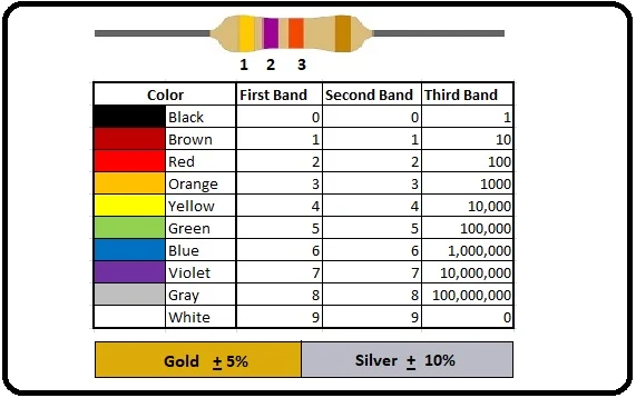
 Resistor Color Code Chart

How to read Resistor Color Code:


Each color has different value we calculate this value using Resistor Color Code Chart.

  • The 1st and 2nd band represent resistor value. 
  • The 3rd band represent multiplier. 
  • And last 4th color gold and silver represent tolerance.


What is resistor
Resistor
We learn resistor value calculation using this picture example.

In this picture Resistor has 4th color.
We know 1st, 2 color represent the resistor value so in color code chart see 1st color value in 1st band and 2nd color value in 2nd band.

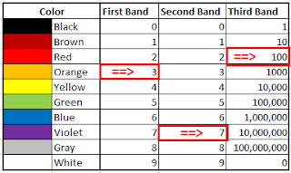
  • 1st color is orange in 1st band orange color value is 3 
    Resistor color code example
    Resistor color code find example
  • 2nd color is violet in 2nd band violet color value is 7

mean 1st two color (orange and violet) value is 37

  • 3rd color is red in 3rd band red color value is 100

we know in resistor 3rd color represent multiplier
so we multiply 1st 2 value (37) with 3rd value (100)
37 x 100 = 3700 ohm
mean this resistor value is 3700 ohm.

  • 4th color is Gold we know its represent Torrance or actual value difference.
We can expect 5% plus and less of actual value (3700 ohm) of the resistor.
if we find 5% of 3700 so answer is 185.
So
185 ohm plus or less in actual value(3700 ohm). 


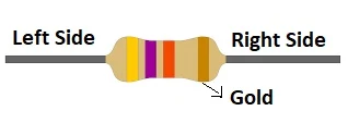
The resistor has 2 sides witch side we start to calculate value?

witch side we start to calculate value
Two side of resistor
It's very simple every time when you calculate any resistor value make sure gold or silver color in your right side. (In picture very clear gold color on right side)
And start calculation with left to right.

Basic idea about LDR Sensor - what is photoresistor

LDR is a light controlled variable resistor. we learn it using 3 steps.
LDR is a light controlled variable resistor.
Basic idea about LDR Sensor
  • Its total depends on light
  • When Light increase LDR resistor decries.
  • And when light decrease then LDR resistor increase.
LDR is stand for Light Dependent Resistor.
we learn it more better watching video.

Video of  Basic idea about LDR Sensor:


Easy Creative Projects

{facebook#https://web.facebook.com/easycreativeprojects/} {twitter#https://twitter.com/easycreativepro} {youtube#https://www.youtube.com/c/easycreativeprojects}

Contact Form

Name

Email *

Message *

Powered by Blogger.
Javascript DisablePlease Enable Javascript To See All Widget