Articles by "electronics-projects"

Convert AC Motor Controller into DC Fan Speed Controller

In this video, we learn how to repurpose a washing machine AC motor speed controller to control the speed of a DC fan. With a few simple diodes and some basic wiring, we turned an old AC controller into a working DC fan speed controller.
Convert AC Motor Controller into DC Fan Speed Controller


This is a great DIY electronics project if you enjoy reusing old parts and exploring practical solutions for motor control. Whether you're into DIY hacks or just want better speed control for your DC fan.

 Components Used:

  • - Washing machine AC motor controller
  • - Diodes 1N4007 to 10A10
  • - DC fan
  • - Basic tools

  1. For the first speed setting, we connected 3 diodes in series
  2. And for the second speed setting, we used 5 diodes in series. 

You can adjust the number of diodes depending on how much you want to reduce the speed. The more diodes you add in series, the greater the voltage drop—and therefore, the slower the fan will run.

We used 1-amp diodes (1N4007) for this setup. However, if your load requires more than 1 amp, it's better to use higher-rated diodes like 10A10 (10-amp diodes).

Video for DC Fan Speed Control Using Washing Machine AC Controller


 How to make 220v universal led tester

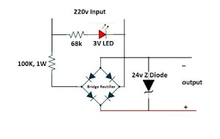
In this project we learn how to make 220v universal led tester easy at home. its very easy and simple project. you can test all type of leds. for making this project we need some components.

Components:

How to make 220v universal led tester
  1. Bridge rectifier
  2. 3 volt LED
  3. 68k resistor
  4. 24v zener diode
  5. 100k, 1 watt resistor
  6.  Shoe switch
  7.  Old tester wire
Now follwing few steps and make same.
  • Connect 1 side of 68k resistor with 3v LED 
  • 2nd side of 68k resistoe and LED use for 220v input.
  • Now 100k 1w resistor connect with 2nd side of 68k resistor.
  • And now connect bridge rectifire. (you can make bridge rectifier using 4 diodes of 1N4007.
  • Finaly connect 24v zener diode. 
we learn it more batter with watching video

Video of homemade 220v universal led tester


Total Cost of 220v universal led tester:

the total cost of this project round about 0.3$
  • shou switch cost roundabout 0.2$ 
  • zener diode cost roundabout 0.01$
  • bridge rectifire cost roundabout 0.04$
  • led cost roundabout 0.01$
  • 68k resistor cost roundabout 0.01$
  • 100k 1w resistor cost roundabout 0.03$


 How to make 5v to 1.5v converter circuit

How to make 5v to 1.5v converter circuit
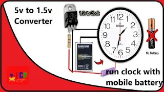
In this project we learn How to make 5v to 1.5v converter circuit easy at home. you can run your wall clock, your calculator and all 1.5v products using this circuit. we make this circuit only 3 componets with the help of circuit diagram. you can also convert your 3.7v mobile and litheam battery with this curcuit. 
for making this project we need some components
  • LM317 Voltage regulator
  • 470ohm resistor
  • 100 ohm resistor
  • soldering wire
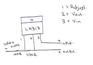
    5v to 1.5v converter circuit diagram

  • soldering iron
Now following this steps and make same
  • LM317 has 3 pin, connect 470 ohm resistor between 1st and 2nd pin of regulator. 
  • Now one side of 100 ohm resistor connect with1st pin of regulator.
  • 2nd side of resistor use for negative input and negative output. 
  • 3rd pin of regulator use for positive input.
  • And 2nd pin of regulator use for positive output.

Video for 5v to 1.5v converter circuit


Total cost of this project:

Total cost of this 1.5v converter circuit is round about 0.105$
  • lm317 voltageregulator price is 0.1$ in local market.
  • And 2 resistor price is 0.005$ in local market.

How to make bike battery charger with in 2 mints

In this porject we learn how to make bike battery charger with in 2 mints. Its very usefull project. Sometime we go for vications and bikes and car are lock for few days. And when we try to on bike that time we need to recharge battery.  That time we really need this charger. 
How to make bike battery charger with in 2 mints
for making this project we need some components. 
  • 12V, 5 Amp Transformer
  • 6A10 Diode
  • 50v, 4700uf Capacitor
  • PCB Board
  • Soldering wire
  • Soldering iron
Now folowing few simple steps and make same.
  • Transformer has 2 side, input side and output side,
  • circuit diagram of bike battery charger
    Input side use for 220 volt power supply, Output side use for 12 volt output.
  • Now take 4 diode and make a bridge rectifier.
  • Take 50v 4700uf capacitor and connect on output DC side of bridge. (Capacitor use for smooth DC power)
  • Now connect transformer with diode bridge.
  • And finally connect 2 wires with capacitor for outputs. 

Video for making bike battery charger:


Total cost of bike battery charger project:

the total cost of bike battery charger project is round about 8.5$
transformer price is 7$, 4 diodes of 6A10 diode price round about 0.8$, 50v capacitor price is round about 0.3$ in local market.

How to charge mobile phone using candle

In this project we learn how to charge mobile phone using candle. we make simple free energy device that generate electricity when we start heating. its one of the best emergency electricity generator and free energy project.
For making this project we need some components. 
How to charge mobile phone using candle

Components:

  • Step up charging module.
  • Peltier module,( i use 6 ampere peltier module) 
  • Candle, 
  • Heat Sink, 
  • Heat Sink Paste.
Now following few simple steps and make same.
  • Peltier has 2 sides. Written side is cold and opposite side is hot. We need hot side.
  • Peltier Red wire use for positive input and black wire use for negative input. Connect both wires with charging module. 
  • Now apply some heat sink paste on peltier. And adjust heat sink on both sides.
  • And now take some iron pieces and make a stand.
  • Now on candle and put it on stand likes this. In cold side I put some ICE for Palter safety.
You don't need any electricity for charging mobile phone. when peltier heat then its generate automatic current and voltage.

Video of free energy device for mobile charging:


Total cost of this project:

total cost of this project round about 2.01$. peltier price roundabout 1.5$, charging module price is 0.5$, candle price is 0.01$ and heatsink you can get from scarp.

 How to recover broken drill machine

In this project we learn how to recover broken drill machine easy at home. our old drill machine casing broken form hand side. we cannot use this casing. so we make new casing with the help of PVC pipe.
for making this project we need some components. 
how to recover broken drill machine

  • 2 inch PVC Tee
  • 2 inch PVC Pipe round about 1 foot
  • 2 inch PVC cap
  • drill machine switch
  • laptop battery cell
  • BMS 12V 20amp or 10amp
  • Machine oil
  • Grease
  • kerosene oil
1st open all screw. if screw hard then apply some WD-40 spray.
Now remove all gears form drill machine.
And now take kerosene oil and clean all parts with the help of brush.
Now dry all parts with the help of cloth.
And now apply some machine oil and grease on all gears.
Now close all parts and apply machine oil and grease time to time.
after successfully close drill machine take 2 inch T and adjust this drill machine on it.
now take laptop battery and make 12v power. 
And now connect BMS for over charge protection. Using this image you can easily connect battery cell with BMS.
And finally make a design as your demand with the help of paint.
for more batter under stand you can watch this video.

Video of recover old broken drill machine:


Total cost of recover broken drill machine project:

  • The total cost of this project is round about 3.7$
  • PVC T price is roundabout 0.5$ 
  • PVC cap price is round about 0.4$
  • PVC pipe price is round about 0.2$
  • Drill machine switch price is round about 0.6$
  • BMS price is round about 1$
  • Old laptop battery price is round about 1$


How to make wall clock easy at home

In this project we learn how to make wall clock easy at home. its very easy useful and money saving project. you can make it under 1 dollar.
for making this project we need some components.
how to make wall clock easy at home

Components list for making wall clock

  • clock machine.
  • hardboard
  • glue gum
  • clock time print
now follow simple steps and make same
  • 1st adjust and fit time print on hard board with the help of glue gum.
  • 2nd open a clock machine and put a hole on hard board center for adjusting clock machine. 
  • And now adjust machine on board.
  • Now put hour, minute, and second, hands.
  • And Finally put cell on clock.

video of homemade wall clock


Total cost of wall clock project.

  • Total cost of wall clock project is round about 0.5$
  • Clock machine price is round about 0.5$
  • Hard board and printer already in my home. so i make full project only 0.5$

 How to make 12v led bulb

in this project we learn how to make 12v led bulb easy at home that directly work on 12v battery or power supply. for making this project we need some components.
how to make 12v led bulb

  • old led bulb
  • 12v led strip (that directly work on 12v)
  • soldering wire
  • soldering iron
now follow simple steps and make same.
  • 1st open old led bulb and remove old circuit and strip.
  • now direct connect new 12v strip. and close led bulb 

video of how to convert old 220v led bulb into 12v led bulb


 how to make electric stove easy at home

In this project we learn how to make electric stove easy at home. its very easy use full and money saving project. for making this project we need some components

  • Heating Element 1000w
    how to make electric stove easy at home
  • Electric Plug
  • 2inch Screw 2
  • Plastic of Paris
  • Round box
Now following these simple step and make same.
  • 1st take a box and put 2 hole on box for electric switch connection.
  •  Now both screw band, and adjust it on electric plug for element connection.
  • Take 1 letter water and 1Kg plastic of Paris, And mix it.
  • After mixing fill it on box.
  • And leave it for 30 mints.
  • Now take a drawing compass and put 3 round holes for heating element fixing
  • Must cut box from switch side because if you don't cut then electricity pass on both side and its very dangerous
  • Now leave it for 3 days on sun light or 1 day on gas burner for completely dry. (its very important if you don't dry then current pass on all plate and its very dangerous.)
  • Finally take a heating element and adjust it on plate. 

video of how to make electric burner easy at home


Total cost of homemade electric burner:

  • Heating element price is round about 0.4$
  • Plastic of Paris price is 0.2$/2kg 
  • screw price is 0.1$/2 piece
  • electric plug price is 0.1$
Total project cost round about 0.8$ maximum.
if you don't find Plastic of Paris so you can use cement and soil.

How to print circuit diagram on pcb board

In this project we learn how to print circuit diagram on pcb board easy at home. for making this project we need some components, 
  • how to print circuit diagram on pcb board
    Toner transfer paper
  • Petrol
  • PCB Board
  • ferric chloride
  • LaserJet printer
Now following few simple steps and make same.
  • 1st take a circuit diagram print on simple paper,
  • Now diagram size cut tonner transfer paper, 
  • And adjust  it on simple paper with the help of tape. 
  • Now adjust this paper on printer. 
  • Cut a PCB board and connect toner transfer paper with the help of tape.
  • Now take a hot iron and leave it for 3 to 5 mint.
  • Put this PCB on water and remove tonner transfer paper, like this. 
  • Now take some ferric chloride and put some water. and shake it.
  • Put PCB Board and leave it for 5 mints.
  • After 5 mints dip it on water.
  • And finally cleaned black ink with the help of petrol.
We learn it more battery with watching video.

video of print circuit diagram on pcb board

Cost of project:

the total cost of project is round about 0.2$
  • Ferric Chloride price is 1$/250gram
  • PCB Board price is 2$/foot
  • Toner transfer paper price is 0.1$/paper

 how to make dc fan speed controller module

In this project we learn how to make dc fan speed controller module up to 10amp dimmer with the help of video and circuit diagram easy at home. for making this project we need some components.

Components list for 10amp dc fan dimmer:

  • NE555 IC
  • 8 PIN IC base
  • how to make dc fan speed controller
    50K VR
  • IRFZ44N
  • Heatsink
  • 1N4148 Diode (3)
  • 50V, 1000UF Capacitor
  • 1K Resistor (2)
  • 10K Resistor
  • 103c
  • 104c
  • 473c
  • PCB Board
  • Soldering wire
  • Soldering iron
now follow simple steps and make same.
  • NE555 IC has 8 pin, connect 4 number pin with 8 number pin,
  • Now connect 6 number pin with 2 number pin, 
  • 4 number pin connect with positive input wire,
  • And 1 number pin connect with negative input wire,

  • Now 1 side of 1k resistor connect with positive wire.
  • Connect 2 diode in seriate 
  • And middle point connect with 2nd side of 1k resistor.
  • Now 1st and 3rd pin of 50k variable resistor connect with 2nd side of both diodes.
  • 7 number pin connect with 2nd side of 1k resistor.
  • Now middle pin of 50k variable resistor connect with 6 number pin.
  • And 104 number capacitor connect with 6 number pin and ground wire.
  • Now 103 number capacitor connect with 5 number pin and ground wire.
  • connect 1 side of 1k resistor  with 3 number pin.
  • And 2nd side connect with 10 k resistor.
  • 2nd side of 1 k resistor connect with ground wire.
  • Now connect 1000 microfarad capacitor between positive and negative wire.
  • 1st wire of mosfet connect with 1k resistor.
  • Now 3 number pin of mosfet connect with ground wire.
  • 473 number capacitor connect with positive wire.
  • Now connect diode with positive wire and 2nd side of 473 capacitor. 
  • Second wire of mosfet connect with diode.
  • and 2nd pin of mosfet also use for negative output.
Using this circuit we can handle upto 10amp dc current. we learn it more batter with watching video.

Video of homemade 10amp dc fan dimmer


Total cost for making dc fan dimmer:

Total cost of this project is round about 1$. all components local market price detail are following

NE555 IC price = 0.13$
8 PIN IC base  = 0.03$
50K VR   = 0.13$
IRFZ44N = 0.2$
Heatsink  = 0.06$
1N4148 Diode (3)  = 0.03$/diode
50V, 1000UF Capacitor = 0.1$
1K Resistor (2) 0.01$/resistor
10K Resistor = 0.01$/ resistor
103c = 0.01$/capacitor
104c = 0.01$/capacitor
473c = 0.02$/capacitor
PCB Board = 0.2$

 how to make 12v fan dimmer easy at home

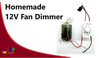
In this project we learn how to make how to make simple 12v fan dimmer easy at home. using this circuit you can control all type of 12v dc motors speed as your demand. 

how to make 12v dc fan dimmer

for making this project we need some components.

Components:

  • 1RFZ44N Mosfet 1
  • 10K Variable Resistor 1
  • Heat Sink 1
  • Old fan dimmer casing
  • Soldering Wire
  • Soldering Iron
Now follow simple steps and make same.
  • 10k variable resistor has 3 pin. connect 2nd pin of variable resistor with 1st pin of mosfet,
    circuit diagram of 12v dc fan dimmer

  • Now 2nd pin of mosfet connect with 3rd pin of variable resistor,
  • 3rd pin of mosfet use for positive output,
  • And 1st pin of variable resistor use for negative output,
  • 1st pin of variable resistor also use for negative input.
  • And 2nd pin of mosfet use for positive input.
  • irfz44n 1st pin is ground, 2nd drain, and 3rd is source

video of  homemade 12v dc fan dimmer


in this project we use only 2 components with very easy and simple circuit diagram. its hold maximum 12v 2amp. for long life work you need to use large heatsink.


How to run RGB multicolor flash led on 220v

In this project we learn how to run RGB multicolor flash led on 220v easy at home with the help of video and circuit diagram. its very simple and interesting project. for making this project we need some components.

Components:
How to run RGB multicolor flash led on 220v
  • RGB Multicolor L E D
  • 47uf, 16 volt capacitor
  • 1N4007 Diode
  • 100 k Resistor
  • Soldering wire
  • Soldering iron
Now following few simple steps and make same.
  • Connect 100k Resistor with one side of 220 volt power supply,
    circuit diagram of how to run multicolor led on 220v
    circuit diagram of how to run multicolor led on 220v
  • And diode cathode side connect with 2nd side of 220 volt power supply like diagram.
  • Now positive side of 47uf capacitor connect with 2nd of resistor
  • And negative side connect with diode anode pin, like diagram,
  • Finally positive side of RGB led connect with positive side of capacitor
  • And negative side connect with negative side of capacitor.
We learn it more batter with watching video.

Video of how to run RBG Multicolor LED on 220v:


How to make 12v powerful emergency electric geyser

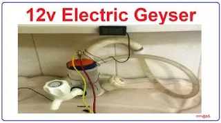
In this project we learn how to make 12v powerful emergency electric geyser easy at home. its very easy and low cast water heater. its specially design for energy saving. in this project we use glow plug. its very high power heating element. normally its use in vehicles engine. but here we use it for water heating. for making this project we need some components.
How to make 12v powerful emergency electric geyser
12v emergency electric geyser

Components:
  • Glow plug
  • Plastic Bottle
  • Tap
Follow simple steps.
  • Put a one hole in the lower side of the bottle.
  • now adjust tap in this hole.
  • Put another hole in the top side of the bottle.
  • now adjust water pipe in this hole.
  • put one hole on the bottle cap.
  • now adjust glow plug in this cap.
  • and now connect cables for power with glow plug. i use old computer power supply. you can use any 12v 2 Amp to 4 Amp power supply.
we learn it more batter with watching video.

video of 12v water heater:


Basic purpose of 12v instant electric geyser:

Basic purpose of 12v instant electric geyser project is that its energy saving. and specially design for 12v power supply. its very easy homemade water heater project.

Some basic Question and Answers:

Can we use this electric geyser with battery power?

Yes we can use this water geyser with any 12v 4 amp battery. we can also use it with bike battery.

How to make automatic DC and AC phase changer switch

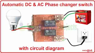
In this project we learn how to make automatic DC and AC phase changer switch easy at home with the help of video and circuit diagram. this switch is specially design for auto switch change. for making this project we need some components.
How to make automatic DC and AC phase changer switch

Components: 

Circuit diagram of automatic line changer switch:

Circuit diagram of automatic line changer switch

  • Take 6 volt 2 relay.
  • both relay 1st pin use for 1st input
  • and both relay 2nd pin use for 2nd input.
  • both relay 5th pin use for output.
  • now connect 1st relay 3 number pin with 4 number pin of 2nd relay.
  • and 1st relay 4 number pin connect 3 number pin of 2nd relay.
  • Finally connect 6 volt power supply with 3 number pin of both relay. (this power supply use for operate the relay.)
we learn it more batter with watching video.

Video of automatic line or phase changer switch:


Basic purpose of automatic line changer switch.

when light goes then we need to on UPS, Generator, or Battery. and change all switches. but using this switch when light goes then its automatically connect with 2nd phase or line. 
in simple word when in 1st input has no power then relay automatically connect with 2nd input switch. and we can get output continually. 

How to run 12v 5w led on 220v

in this project we learn how to run 12v 5w led bulb on 220v easy at home using few simple steps with circuit diagram. its very cheapest, easy and homemade electronic project. for making this project we need some components.

How to run 12v 5w led on 220v
Components:
  • 12 volt 5 watt led bulb (1)
  • 400V 1uf Polyester Capacitor (1)
  • 1M 1 watt Resistor (1)
  • 47 ohm 1 watt resistor (1)
  • 25v 100uf capacitor (1)
  • 1N4007 Diode (5)
  • PCB Board
  • Soldering wire
  • Soldering iron
  • old energy saver
  • hot glue gun
In this project we use 400 volt and 1uf polyester capacitor. in market its also know as 105J number capacitor. 

Circuit Diagram of how to run 12v 5w led on 220v:

circuit diagram of run 12v 5w led on 220v


  • Connect 400v,1uf capacitor with 1M resistor.
  • one side of 400v capacitor connect with 220v live wire.
  • Take a 4 diode of 1N4007 and make a diode bridge like diagram.
  • diode bridge provide us 4 connection. 2 input connection and 2 output connection.
  • one input connection connect with 400v capacitor. 
  • and 2nd input connection connect with 220v live wire.
  • now connect 25v, 100uf capacitor with output pins of diode bridge.
  • now connect one side of 47 ohm resistor with positive side of capacitor.
  • and 2nd side of resistor connect with positive side of 12v led.
  • and finally 2nd side of led connect with negative side of capacitor.

adjust led on energy saver


  • Now connect all component on PCB Board using circuit diagram.
  • now take old energy saver and adjust this pcb circuit on energy saver using hot glue gun.


its very easy and simple circuit. all components you can get from electronic shop very easily. we learn it more batter with watching video.

Video of run 5 watt led on 220v :


in conclusion its simple low cost homemade energy saving project. you can use this LED Bulb on house store, house terrace, or any low light place. its easy long life and durable project. you can direct run it on 220v power supply. you can also run it with UPS.

How to make telephone easy at home

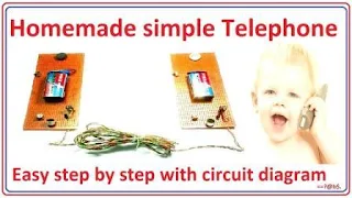
In this project we learn how to make telephone easy at home using simple few steps with circuit diagram. basically its simple combination of speaker and mic. and transistor use for amplifier audio. 
for making this project we need some components.
How to make telephone easy at home

Components of making telephone:

  • 2n2222a Transistor (2)
  • Mic (2)
  • Speaker (2)
  • On/Off Button (2)
  • 10k Variable Resistor (2)
  • 9v Battery (2)
  • 9v Battery Clips
  • PCB Board (2)
  • Cable wire (2)
  • Clip Connector (2)
  • Soldering Wire
  • Soldering iron (how to make soldering iron)

Circuit diagram of telephone:

How to make telephone circuit diagram
  • 2n2222a NPN Transistor has 3 pin. 1st emitter, 2nd base, and 3rd collector.
  • Connect negative side of speaker wire with collector pin.
  • 10k variable resistor has 3 pin. 
  • 1st pin connect with positive side of speaker wire.
  • Middle pin connect with base pin of transistor.
  • 3rd pin connect with mic. 
  • and 2nd side of mic connect with emitter pin of transistor.
  • Positive side of 9v battery connect with speaker positive pin.
  • and negative side of battery connect with transistor emitter pin.
  • finally connect on/off button between positive wire of battery.
follow same procedure and make 2 set.
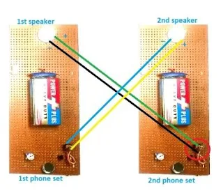
phone set connection diagram
  • now 1st phone speaker connect with 2nd phone using wire.
  • and 2nd phone speaker connect with 1st phone using wire.  
we can better understand with this picture.
in this picture we make 2 phone set.
and replace speaker connection with clip connector. 
now connect 1st speaker with one side of wire. and 2nd side of wire connect with 2nd phone set using clip connector.
similarly 2nd speaker connect with one side of wire and 2nd side of wire connect with 1st phone using clip connector.
we learn it more better with watching video.

Video of how to make telephone set:


it is the basic electric telephone set project. you can also use it as a door security system.
simply one set connect outside of main door and 2nd set connect with inside of house.

How to make wireless mobile phone with dialing number

In this project we learn how to make wireless mobile phone with dialing number easy at home using few simple steps with circuit diagram.
homemade wireless mobile phone with dialing number
basically this project is the combination of two projects.
  1. How to make wireless phone set easy at home
  2. How to make simple key code lock switch circuit.
in this project we combined both project and use key code lock switch as a dialing number.

Circuit diagram:

wireless mobile phone with dialing number circuit diagram

simple connect relay switch with wireless power wire. like circuit diagram.
learn it more batter with watching video.

video of wireless mobile phone with dialing number:


How to make simple key code lock switch circuit

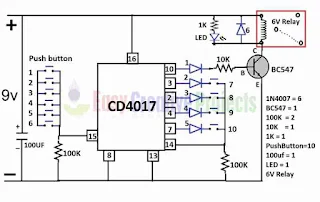
In this project we learn how to make simple key code lock switch circuit easy at home using few simple steps with circuit diagram. in this project we use CD4017 IC. its best for this project.
How to make simple key code lock switch circuit
homemade simple key code lock switch circuit
for making this project we need some components.

Components: 
  • CD4017 IC
  • IC Base
  • 6V Relay
  • 16v 100uf capacitor
  • BC547 NPN Transistor
  • Push Buttons (10)
  • 1K Resistor
  • 10K Resistor
  • 100K Resistor (2)
  • 1N4007 Diode
  • 1N4148 Diodes (5)
  • LED
  • 9V Battery
  • Battery Clip
  • PCB Board
  • Soldering Iron
  • Soldering wire
CD4017 basically counting base ic. we can use it for low range counting projects.

Key Code Lock Switch Circuit Diagram:

  • CD4017 IC has 16 pins.
    simple key code lock switch circuit diagram
    simple key code lock switch circuit diagram
  • Connect anode side of 1st 4148 diode with 10 number pin and cathode side connect with 10k resistor.
  • and connect 2nd side of 10 resistor with base pin of BC547 transistor.
  • now connect anode side of 2nd 4148 diode with 3 number pin and cathode side connect with push button.
  • connect anode side of 3rd 4148 diode with  2 number pin and cathode side connect with push button.
  • next connect anode side of 4th 4148 diode with 4 number pin and cathode side connect with push button.
  • connect anode side of 5th 4148 diode with 7 number pin and cathode side connect with push button.
  • now connect 14 number pin with 2nd sides of all push buttons. 
  • connect 100K resistor with 14 number pin.
  • and 2nd side of 100k resistor connect with ground wire. 
  • and connect 8 number pin and 13 number pin with ground wire.
  • connect 15 number pin with 100k resistor.
  • and 2nd side of 100k resistor with ground wire.
  • BC547 emitter pin connect with ground wire.
  • and collector pin connect with 6v relay coil pin.
  • 2nd side of relay coin pin connect with 16 number ic pin.
  • 16 number ic pin use for positive power.
  • connect 1N4007 diode with relay coil pins.
  • now connect 1k resistor and LED with relay coil pins like diagram.
  • connect 16v 100uf capacitor with positive and negative wire.
  • and finally connect 9v power with positive and negative wire. ( positive wire connect with 16 number pin. and negative wire connect with 13 number pin.)
we learn it more batter with watching video.

Video of homemade key code lock switch circuit:


in conclusion its simple password security for electronic device using ic 4017 project. you can use it for any electronic project. 

How to make wireless phone set easy at home

In this project we learn how to make wireless phone set easy at home using a few simple step with circuit diagram. so this project divided in two parts. 1st part we make sending device circuit and in 2nd part we make receiving device circuit. This project work on radio fm frequency.

Before making wireless phone set project you need to learn these two project. then you can make this project very easily.
homemade wireless phone set
Homemade wireless phone set


1st Part of wireless phone set:

in 1st part we make wireless phone sending device and circuit. using this circuit we can send our voice on wireless waves frequency.

Components: 
  • SN74LS13N IC
  • IC Base
  • Mic
  • LM7805 Voltage Regulator(for 5v output)
  • 104pf Capacitor
  • 103pf Capacitor
  • 22pf Capacitor
  • 4.7k Resistor (2)
  • PCB Board
  • LED
  • 9V Battery
  • Battery clip
  • Soldering wire
  • Soldering iron

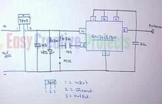
Wireless Sending Device Circuit Diagram:

Wireless receiving device circuit diagram
Wireless sending device circuit diagram
For sending device we use SN74LS13N IC for sending data. its convert our voice into radio signal. following few steps and make transmitter circuit.


  • Connect 1,2,4, and 6 number pin with each other.
  • now connect antenna with 6 number pin.
  • connect 22 number capacitor with 6 and 7 number pin.
  • connect 1st side of 4.7k resistor with 14 number pin.
  • now connect 1st side of 104 number capacitor with 5 number pin.
  • connect 2nd side of 4.7k resistor and 104 number capacitor with each other. 
  • now connect MIC with ground wire and 2nd side of 4.7k resistor. 
  • connect 4.7k resistor and LED with positive and negative wire.
  • now connect 103 number capacitor with positive and negative wire.
  • LM7805 has 3 pins.
  • connect 9v positive wire with 1st pin of voltage regulator.
  • now connect negative wire of 9v battery with 2nd pin of voltage regulator.
  • voltage regulator 3rd pin use for 5v positive output.

2nd Part of wireless phone set:

In 2nd part we make wireless phone receiving device and circuit. using this circuit we can receive our voice from waves and convert into on speaker.

Components:
  • TA2003P IC
  • 16 Pin IC Base
  • 15pf Capacitor
  • 471pf Capacitor
  • 4.7uf, 25v Capacitor
  • 220uf 25v Capacitor
  • 2pin 10.7MHz Ceramic Filter
  • 3pin 10.7MHz Ceramic Filter
  • Variable Capacitor or Tuner
  • 26Gauge 4 turn and 5 turn coil
  • PCB Board
  • 2n2222a NPN Transistor
  • 1K Variable resistor
  • ON/OFF Switch
  • Speaker
  • Soldering wire
  • Soldering iron ( how to make soldering iron)

Wireless receiving device circuit diagram:

Wireless receiving device circuit diagram
For receiving device we use TA2003P ic this ic use for receiving signal from fm frequency. flowing few steps and make receiver circuit.
  • TA2003P IC has 16 pin.
  • connect antenna with 1 number pin.
  • now connect negative power with 2 number pin. 
  • connect 3 pin ceramic filter with 3,6 and 8 number pin.
  • 6 number pin use for positive power supply. (you can use 3v to 5v power supply)
  • connect 5turn coin with 15 number pin and positive power.
  • now connect 14 number pin with positive power.
  • connect 15 number capacitor and 4 turn coil with 13 number pin and positive power.
  • now connect 471 number capacitor with 11 number pin and positive power.
  • connect 2pin ceramic filter with 10 number pin and positive power.
  • now connect 9 number pin with emitter of 2n2222a transistor.
  • connect speaker with collector pin of 2n2222a transistor and 3rd pin of variable resistor.
  • 2nd pin of variable resistor connect with base.
  • connect 220uf negative side of capacitor with 1st pin of 1K variable resistor.
  • and positive side of capacitor connect with negative side of 4.7uf capacitor.
  • and 2nd side of 4.7uf capacitor connect with 11 number pin.

Now combined both Parts:

sending device work on 5v power supply Now take a PCB board and connect sending device circuit components and receiving device circuit components.
Complete circuit diagram of wireless phone set

  • and receiving device also work on 5v power supply.
  • so connect both parts power connection with 5v voltage regulator ( LM7805).
  • wireless phone set
    Wireless phone sets
  • now connect 9v power cell for input power. (Positive wire connect with 1st pin of LM7805 and negative wire connect with 2nd pin of LM7805)
now follow hole project and make 2 sets like picture. because you need 2 set for talking. 
now adjust frequency using variable capacitor. 
here we use variable capacitor. you can control sound using variable capacitor. 

we learn it more batter with watching video.

Video of  How to make wireless mobile phone set:


If you want to make it more advance so you can follow below link.
How to make wireless mobile phone with dialing number

Easy Creative Projects

{facebook#https://web.facebook.com/easycreativeprojects/} {twitter#https://twitter.com/easycreativepro} {youtube#https://www.youtube.com/c/easycreativeprojects}

Contact Form

Name

Email *

Message *

Powered by Blogger.
Javascript DisablePlease Enable Javascript To See All Widget