Articles by "power-supply"

How To Fix Power Supply Load Issue Using One Part

In this project we learn how to fix power supply load issue using one part. With this method, you can easily fix the issue of power drop. Sometimes the power supply doesn’t work properly. it keeps turning on and off. 
How To Fix Power Supply Load Issue Using One Part

This usually happens when we connect something heavy like a motor that needs more current than the power supply can give. Because of that, the device doesn’t run smoothly and keeps restarting. 

To fix this, we did a little trick. We added a 22k resistor to the input side of the optocoupler inside the power supply. This makes the power supply think the load is not too heavy, so it sends more current to the output. 
Increase Current Output Easily


Basically, we messed with the feedback system a bit. By changing the resistor to 22k, the power supply gives more amps, which helps run heavy loads properly without tripping. It’s like a small hack to increase the output limit.

video for fixing power supply load issue


How to make bike battery charger with in 2 mints

In this porject we learn how to make bike battery charger with in 2 mints. Its very usefull project. Sometime we go for vications and bikes and car are lock for few days. And when we try to on bike that time we need to recharge battery.  That time we really need this charger. 
How to make bike battery charger with in 2 mints
for making this project we need some components. 
  • 12V, 5 Amp Transformer
  • 6A10 Diode
  • 50v, 4700uf Capacitor
  • PCB Board
  • Soldering wire
  • Soldering iron
Now folowing few simple steps and make same.
  • Transformer has 2 side, input side and output side,
  • circuit diagram of bike battery charger
    Input side use for 220 volt power supply, Output side use for 12 volt output.
  • Now take 4 diode and make a bridge rectifier.
  • Take 50v 4700uf capacitor and connect on output DC side of bridge. (Capacitor use for smooth DC power)
  • Now connect transformer with diode bridge.
  • And finally connect 2 wires with capacitor for outputs. 

Video for making bike battery charger:


Total cost of bike battery charger project:

the total cost of bike battery charger project is round about 8.5$
transformer price is 7$, 4 diodes of 6A10 diode price round about 0.8$, 50v capacitor price is round about 0.3$ in local market.

How to make 5v adjustable current power supply

In this project we learn how to make 5v adjustable current power supply easy at home with the help of video and simple circuit diagram. in this project we also use LM7805 voltage regulator for regulate voltage. you can easily adjust current with variable resistor. For making this project we need some components,

Components:
  • 24v or 12v 10 amps Transformer
  • LM7805 Voltage regulator
  • TIP3055 Transistor
  • BD139 Transistor
  • 35v, 220uf capacitor
  • 35v, 4700uf capacitor
  • 10A10 diode
  • 10K Variable resistor
  • Heatsink
  • 1N4007 diode
  • Soldering wire
  • Soldering iron
  • PCB Board
Now following few simple steps and make your own power supply,
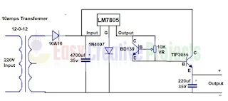
5v adjustable current power supply circuit diagram
  • Transformer has 2 side, 1st side called primary and 2nd side called secondary
  • Primary side or primary winding use for 220v input power supply
  • If you use 12-0-12 transformer then you can see 3 wires connection, 
  • Connect 10A10 diode with 1st wire of transformer.
  • Now leave 2nd wire and 3rd wire use for ground wire,
  • 35v, 4700uf capacitor has 2 pin,
  • Positive pin connect with 2nd side of 10A10 diode and negative side connect with ground wire.
  • Now input wire of LM7805 voltage regulator connect with 2nd side of diode
  • 1N4007 diode connect with ground wire of voltage regulator and ground wire. 
  • Now collector pin of BD139 connect with output wire of voltage regulator, 
  • Variable resistor has 3 pin,
  • Middle pin connect with base of bd139, 
  • 1st and 3rd pin connect with collector and emitter pin, like diagram, 
  • Now TIP3055 transistor base pin connect with emitter of bd139 transistor 
  • And collector pin connect with input pin of voltage regulator,
  • Now positive side of 35v, 220uf capacitor connect with emitter pin of TIP3055 transistor,
  • And negative side of capacitor connect with ground wire,
  • Finally emitter pin of TIP3055 transistor use for positive output and ground wire use for negative output.
 BD139 NPN Transistor has 3 pin 
  • 1st emitter 
  • 2nd collectors
  • 3rd base

TIP3055 has 3 pin
  • 1st base 
  • 2nd collector
  • 3rd emitter
We learn it more batter with watching video.

Video of how to make 5v variable current power supply:


More related links

How to make 12v adjustable current power supply

In this project we learn how to make 12v adjustable current power supply easy at home with the help of video and circuit diagram. using this circuit you can adjust current 0.1 ampere to 10 ampere and voltage fix 12 volt. Because we also use LM7812 voltage regulator for regulate voltage.
For making this project we needs some components.
How to make 12v adjustable current power supply

Components:

  • 12v or 24v 10 amps Transformer
  • TIP3055 Transistor
  • LM7812 Voltage Regulator,
  • BD139 Transistor,
  • 4700uf, 35v Capacitor,
  • 220uf, 35v Capacitor,
  • 10k Variable Resistor,
  • 10A10 diode,
  • 1N4007 diode,
  • Heat Sink,
  • Soldering wire,
  • Soldering iron, 
  • PCB Board
1st make circuit diagram, 
  • Transformer has 2 side, 
    12v adjustable current power supply circuit diagram
    12v adjustable current power supply circuit diagram
  • Primary side use for 220 volt input power, 
  • Secondary side has 3 pin, 
  • Connect 10A10 diode with 1st pin of transformer, 
  • If you use 12-0-12 transformer then leave 2nd wire and 3rd wire use for ground wire, 
  • Now positive side of 4700uf capacitor connect with 2nd side of diode, 
  • And negative side connect with ground wire, 
  • Now input wire of voltage regulator connect with 2nd side of diode,
  • And 1N4007 diode connect with ground wire of voltage regulator like diagram. 
  • Now collector pin of BD139 transistor connect with output wire of voltage regulator,
  • Variable resistor has 3 pin.
  • Middle pin connect with base of BD139,
  • 1st and 3rd pin connect with collector and emitter pin of BD139, like diagram,
  • Now TIP3055 transistor base pin connect with emitter of BD139,
  • And now collector pin connect with input pin of voltage regulator,
  • Now positive side of 220uf capacitor connect with emitter pin of  TIP3055,
  • Negative side of capacitor connect with ground wire, 
  • And finally emitter pin of tip3055 use for positive output and ground wire use for negative output. 

BD139 NPN Transistor has 3 pin.
  • 1st Emitter 
  • 2nd Collectors
  • 3rd Base
TIP3055 NPN Transistor has 3 pin. 
  • 1st Base
  • 2nd Collector
  • 3rd Emitter
We learn it more battery with watching video.

Video of how to make 12v adjustable current power supply:


Why TIP3055 Transistor very heating?

When we adjust current then total load transfer on Transistor and transistor very heat up. So must use large heat sink with transistor. and also use cooling fan. if you dont do this then your transistor burn soon.

How we adjust current?

you can adjust current using 10k variable resistor 0.1 amps to 10 amps. for example if our requirement is 2 ampere then simple adjust it in 2 amps with the help of multi meter.

How to make 15v 3 amp power supply

In this project we learn how to make 15v 3 amp power supply easy at home with the help of video and circuit diagram. its very easy and useful homemade project. in this project we also use LM7815 voltage regulator for regulate voltage of fix 15 volt. for making this project we need some components.
How to make 15v 3 amp power supply

Components:
  • 12-0-12 or 24v 3Amp Transformer
  • D313 Transistor
  • LM7815 Voltage Regulator
  • 35v 1000uf capacitor
  • 35v 220uf capacitor
  • 1N5408 Diode
  • 1N4007 Diode
  • PCB Board
  • Soldering Iron
  • Soldering Wire
Now following few simple steps and make same.
  • Transformer has 2 side.
    15v 3 amp power supply circuit diagram
    15v 3 amp power supply circuit diagram
  • Primary side use for 220 volt power supply. 
  • Secondary side has 3 pin.
  • Connect 1N5408 diode with 1st pin of transformer, if you use 12 volt transformer then leave 2nd pin and use 3rd pin for ground wire. 
  • Now connect positive side of 1000uf  capacitor with 2nd side of diode.
  • And negative side connect with ground wire. 
  • Now input wire of voltage regulator connect with 2nd side of diode,
  • And now 1N4007 diode connect with ground wire of voltage regulator like diagram, 
  • Now output wire of voltage regulator connect with base of transistor, 
  • And now collector pin of transistor connect with input wire of voltage regulator,
  • Now positive side of 220uf capacitor connect with emitter pin of transistor,
  • And negative side of capacitor connect with ground wire, 
  • Finally emitter pin use for 15 volt positive output and ground wire use for negative output. 
D313 transistor has 3 pin, 
  • 1st Base 
  • 2nd Collector
  • 3rd Emitter
We learn it more batter with watching video:

Video of how to make 15v 3 ampere power supply:


Some Basic Question and Answers

Why use D313 Transistor?

D313 Transistor work on 3 ampere power so we use it for making 3amp power supply.

Why output current is less then 3 ampere?

its total problem from transformer. when we buy 3 ampere transformer in actual its 2.5 ampere or more less. because shops or company maker doing fraud. They use low quality and low power wire in transformer. So its provide us low current. wire current rating chart

How to make 5v 10 amp power supply

in this project we learn how to make 5v 10 amp power supply easy at home with the help of video and simple circuit diagram. in this project we also use lm7805 voltage regulator for regulate voltage of fix 5 volt. for making this project we need some components.
How to make 5v 10 amp power supply
Components:
  • 12v 10 amp transformer
  • Tip3055 transistor
  • LM7805 Voltage regulator
  • Heat sink
  • 10A10 Diode (2)
  • 1N4007 Diode
  • 35v, 4700uf capacitor
  • 35v 220uf capacitor
  • PCB Board
  • Soldering Iron
  • Soldering Wire
Now following these few simple steps and make same.
  • 12-0-12 or 12v transformer has 2 side
    5v 10 amp power supply circuit diagram
    5v 10 amp power supply circuit diagram
  • 1st is primary and 2nd is secondary
  • Primary side use for 220v input power supply,
  • Secondary side ha 3 pin, connect anode sides of 10A10 diode with 1st and 3rd pin of transformer. like diagram
  • And 2nd side or cathode side of both diode connect with each other. 
  • Transformer Middle wire is use for ground wire.
  • Now Positive side of 4700 uf capacitor connect with diode cathode pin. 
  • And negative side of capacitor connect with ground wire.
  • Now connect input wire of LM7805 voltage regulator with positive wire of 4700uf capacitor, 
  • And connect 1N4007 diode with ground wire of voltage regulator like diagram, 
  • Now output wire of voltage regulator connect with base of TIP3055 transistor, 
  • And collector pin of transistor connect with positive side of 4700 micro farad capacitor,
  • Now positive side of 220uf capacitor connect with emitter pin of transistor and negative side connect with ground wire. 
  • Finally emitter pin of transistor use for positive 5v output and ground wire use for negative 5v output.
Tip3055 transistor has 3 pin.
  • 1 pin use for base
  • 2nd pin use for collector
  • 3rd pin use for emitter
we learn it more battery with watching video

Video of how to make 5v 10 amp power supply:


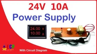
In this project we learn how to make 24v and 10amp power supply easy at home with the help of circuit diagram and few simple steps. in this project we also use lm7824 voltage regulator for regulate voltage. for making this project we need some components.
How to make 24v and 10amp power supply easy at home

Components:

  • 24v 10amp transformer
  • Tip3055 transistor
  • LM7818 Voltage regulator
  • Heat sink
  • 10A10 Diode (2)
  • 1N4007 Diode
  • 50v, 4700uf capacitor
  • 50v 470uf capacitor
  • PCB Board
  • Soldering Iron
  • Soldering Wire
now following few simple steps.
  • take a 24v 10 amp transformer, we can use 12v two output transformer.
  • Transformer has 2 side, (Primary and Secondary) 
    24v 10 amp power supply circuit diagram
    24v 10 amp power supply circuit diagram
  • Primary side use for 220 volt input power supply. 
  • Secondary side has 3 wires. 
  • 10A10 diode connect with 1st and 3rd wires of transformer. 
  • And 2nd sides of both diodes connect with each other. 
  • Transformer middle or center wire use for ground wire or negative wire. 
  • Now connect positive side of 4700 micro farad capacitor with 2nd sides of diode, and negative side connect with ground wire of transformer. 
  • And now connect input wire of voltage regulator with positive wire of 4700 micro farad capacitor, 
  • Now connect 1N4007 diode with ground wire of voltage regulator like diagram, 
  • And now output wire of voltage regulator connect with base of transistor, 
  • Now collector pin of transistor connect with positive side of 4700 micro farad capacitor,
  • And now positive side of 470 micro farad capacitor connect with emitter pin of transistor and negative side connect with ground wire. 
  • Finally emitter pin of transistor use for positive output and ground wire use for negative output.
Tip3055 transistor has 3 pin.
  • 1 pin use for base
  • 2nd pin use for collector
  • 3rd pin use for emitter
We learn it more batter with watching video.

Video of making 24v 10 amp power supply:


 How to make 18v and 10amp power supply

In this project we learn how to make 18v and 10amp power supply easy at home using few simple steps with the help of video and circuit diagram. normally voltage regulator provide us 1 ampere output current. but we get our desire current with the help of single transistor.
How to make 18v and 10amp power supply
for making this project we need some components.

Components:
  • 24v 10amp transformer
  • Tip3055 transistor
  • 10A10 Diode (2)
  • 1N4007 Diode
  • LM7818 Voltage regulator
  • Heat sink
  • PCB Board
  • Soldering Iron
  • Soldering Wire
  • 50v, 4700uf capacitor
  • 50v 40uf capacitor
Now follow few simple steps and make your own power supply.
18v 10 amp power supply circuit diagram
  • 24 volt 10 ampere transformer has 2 side, 
  • Primary side use for 220 volt input power supply. 
  • Secondary side has 3 wires. 
  • Connect 10A10 diode with 1st and 3rd wires of transformer. 
  • And 2nd sides of both diodes connect with each other. 
  • Transformer middle wire use for ground wire. 
  • Now connect positive side of 4700 micro farad capacitor with 2nd sides of diode, and negative side connect with ground wire of transformer. 
  • And now connect input wire of voltage regulator with positive wire of 4700 micro farad capacitor, 
  • Now connect 1N4007 diode with ground wire of voltage regulator like diagram, 
  • And now output wire of voltage regulator connect with base of transistor, 
  • Now collector pin of transistor connect with positive side of 4700 micro farad capacitor,
  • And now positive side of 470 micro farad capacitor connect with emitter pin of transistor and negative side connect with ground wire. 
  • Finally emitter pin of transistor use for positive output and ground wire use for negative output.
Tip3055 transistor has 3 pin.
  • 1 pin use for base
  • 2nd pin use for collector
  • 3rd pin use for emitter
Its very simple homemade and very powerful high current power supply. we learn it more better with watching video

Video of  how to make 18v 10amp dc power supply:


How many voltage and current we get form 10A10 diode?

we can get 1000 volt and 10 ampere current from 10A10 diode.

How to make 12v and 10amp power supply easy at home

In this project we learn how to make 12v and 10amp power supply easy at home using few simple steps with the help of circuit diagram. for making this project we need some components.
How to make 12v and 10amp power supply easy at home

Components:
  • 12v 10amp Transformer
  • TIP3055 Transistor
  • LM7812 Voltage Regulator
  • 4700uf, 35v Capacitor
  • 220uf, 25v Capacitor
  • 1N5408 Diode (2)
  • 1N4007 Diode
  • Heat Sink (2)
  • PCB Board
  • Soldering wire
  • Soldering iron
in this project we use LM7812 voltage regulator. Normally its provide us only 1amp output. but we use transistor for increase power. follow these simple steps and make your own power supply.
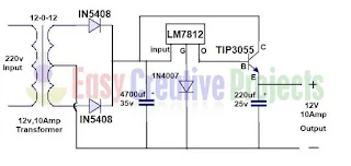
12 volt 10 amp power supply circuit diagram

  • Transformer has 2 side primary side use for 220 volt input power supply.
  • Secondary side has 3 wires. 
  • Connect 1N5408 diode with 1st and 3rd wires of transformer. Like diagram. 
  • And 2nd sides of both diodes connect with each other. 
  • Transformer middle wire use for ground wire.
  • Now connect positive side of 4700 micro farad capacitor with 2nd sides of diode, and negative side connect with ground wire of transformer.
  • And now connect input wire of voltage regulator with positive wire of 4700 micro farad capacitor. 
  • Now connect 1N4007 diode with ground wire of voltage regulator like diagram,
  • And now output wire of voltage regulator connect with base of transistor, 
  • Now collector pin of transistor connect with positive side of 4700 micro farad capacitor,
  • And now positive side of 220 micro farad capacitor connect with emitter pin of transistor and negative side connect with ground wire. 
  • And finally emitter pin of transistor use for positive output and ground wire use for negative output.
TIP3055 transistor has 3 pin.
  • 1st is Base
  • 2nd Collector
  • 3rd Emitter
we learn it more battery with watching video

Video of how to make 12v 10amp power supply:


Some basic Question and Answers:

Why we chose TIP3055 Transistor for 12v 10amp power supply?

Because we can get 15 ampere current form TIP3055 transistor so we chose this transistor.

How do you make a 12 volt battery charger 5 amp? 

simple use this circuit and replace this transformer with 5 ampere transformer.

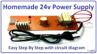
How to make 24v adapter or DC power supply easy at home

In this project we learn how to make 24v adapter or dc power supply easy at home using few simple steps with the help of circuit diagram. its very simple useful and homemade project. if you follow these steps then you can easily build your own 24v power supply.
make 24v adapter or DC power supply
how to make 24v DC power supply
for making this project we need some components.

Components for making 24v adapter:
  • 12-0-12 or 24V 1 Amp Transformer
  • LM7824 Voltage regulator
  • Heat sink
  • 50v 1000uf capacitor
  • 1N4007 Diode (4)
  • LED
  • 1K 1/4W Resistor
  • PCB Board
  • Soldering wire
  • Soldering iron

Circuit Diagram of how to 24v dc power supply:

24v power supply circuit diagram

  • Transformer has 2 side. one side is use for input and 2nd side is use for output.
  • input side of transformer connect with 220v direct power.
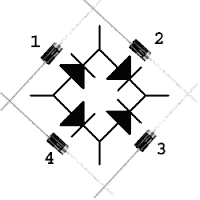
Diode bridge circuit diagram

How to make diode bridge:

  • Take a 4 diodes of 1N4007.
                1: 1st diode head connect with 2nd diode tail
                2: and 2nd diode head connect with 3rd diode head.
                3: and 3rd diode tail connect with 4th diode head.
                4: and 4th diode tail connect with 1st diode tail
  • Output side of transformer connect with diode bridge. 
               1 wire connect between 1 and 2 number
               2nd wire connect between 3 and 4 number.
  •  Now connect 50v, 1000uf capacitor with diode bridge.
              1: positive side of capacitor connect between 2 and 3 number pin.
              2: negative side connect between 1 and 4 number pin.

  • Now connect 1k resistor and LED with positive and negative wire. 
  • Now take LM7824 Voltage regulator.
lm7824 pinout diagram
LM7824 pinout diagram
  • LM7824 has 3 pin.
              1: 1st is use for input
              2: 2nd pin is use for ground
              3: 3rd is use for output


  • Now 1st pin of voltage regulator connect with positive side of capacitor. or positive side of wire. 
  • 2nd pin of voltage regulator connect with ground wire. or negative side of capacitor.
  • 3rd pin of voltage regulator is provide you 24v positive power
  • and 2nd pin of voltage regulator is use for negative power or ground wire. like diagram.
these are few steps if you follow properly then you easily make LM7824 power supply circuit. we learn it more battery with watching video.

Video of how to make homemade 24v dc power supply:


we try to explain every thing with easy simple steps with video and circuit diagram. simple follow circuit diagram and make this project.


How to make mobile charger easy at home

In this project we learn how to make mobile charger easy at home. its very useful easy and homemade electronic project. for making this project we need some components.

Components:
  • 9v 1 amp Transformer
  • LM7805 Voltage Regulator
  • Heat sink
  • 25v 1000uf capacitor
  • 1N4007 Diode (4)
  • 1K, 1/4W Resistor (what is resistor)
  • LED
  • USB Female Connector
  • PCB Board
  • Soldering Iron (how to make soldering iron)
  • Soldering Wire
In this project we use LM7805 voltage regulator. its perfect for our project. transformer use for convert 250 volt to 9 volt. you can use 9 volt to 24 volt any transformer. because voltage regulator provide us fix 5 volt output. 

How to make mobile charger circuit:

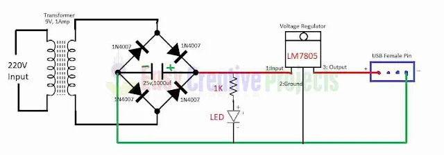
how to make mobile charger circuit diagram
circuit diagram of mobile charger
Simple follow circuit diagram that very help us to understand that how to make a phone charger.  for making smart cell phone charger follow few instructions.

  • Take 9 volt and 1 ampere transformer. input side use for direct 220 volt power.
  • take 4 diodes and make a diode bridge. like diagram. 
  • now connect 2 side with output transformer like circuit diagram.
  • and now connect 25 volt 1000uf capacitor with other two sides of diode like circuit diagram. 
  • now connect 1 K resistor and LED with positive and negative output wires. like diagram.
  • LM7805 voltage regulator has 3 pins. 
  • 1st is input, 2nd ground, and 3rd is output. 
  • connect input wire with positive wire that come from diode. (or connect input wire with positive side of capacitor.) 
  • now connect ground wire with negative wire that come from diode bridge. like diagram.
  • connect 3rd pin with 1st side of USB Female pin. 
  • and connect negative wire with 2nd side of USB female pin.
we learn it more batter with watching video.

Video of how to make smart phone charger : 


In conclusion its very easy, powerful, long life homemade portable phone charger project. using this circuit you can charger Nokia, Samsung, iPhone, Apple, Microsoft, LG, HTC, Huawei, Sony, Lenovo, Oppo and all companies mobile.

How to make 12v power supply easy at home

In this project we learn how to make 12v power supply easy at home or how do i convert 230v into 12v DC using few simple steps with circuit diagram. for making this project we need some components.

Components Required for making 12v Adapter:

  • LM7812 Voltage Regulator
  • Heat Sink
  • 50v 1000uf (Capacitor)
  • LED
  • 1K Resistor
  • 1N4007 (4 Diodes)
  • 12-0-12 (12v/1 Ampere Transformer)
  • PCB Board
  • Soldering Iron
  • Soldering Wire
In this project we use LM7812 voltage regulator. main function of voltage regulator is give us exactly 12v output.
We use diode bridge because its convert AC volt to DC volt.

12v power supply circuit diagram

Make 12v Power Supply Circuit Diagram:

  • Take 4 Diodes and make a bridge, like diagram.
  • Connect transformer output with diode, like diagram.
  • Now connect 1000uf capacitor positive wire connect with positive wire and negative side connect with ground wire.
  • and now connect 1k resistor and LED with positive and negative wire.
  • Now voltage regulator 1st pin connect with positive wire 2nd pin connect with ground wire and 3rd pin use for output.
  • Voltage regulator 2nd (- 12v) and 3rd (+12) pin use for output power supply.
  • Finally connect Heat Sink with voltage regulator.
LM7812 pin out diagram
LM7812 Voltage Regulator

LM7812 Voltage Regulator Pin out:

LM7812 voltage regulator has 3 pin.
  • 1st Input
  • 2nd Ground
  • 3rd Output
main function of voltage regulator its provide exactly 12v output.
for example if input is 20v and i want exactly 12v output then i use LM7812.
Learn more with watching video

Video of how to make 12v Power Adapter:


Some basic Question and Answers:

Why use Diode bridge?

Because we are making DC power supply and  transformer provide us AC power so we use diode bridge for ac to dc converter. we can also use voltage rectifier. both works are same. if you cannot find voltage rectifier then you can use diode bridge.

Why use transformer?

because our requirement is input voltage 220 volt and output voltage 12v. and transformer convert 220 volt power into 12v. Here basic purpose of the transformer is, its reduce power in 220v to 12v.

what is the meaning of 12-0-12 Transformer?

12-0-12 transformer mean 12v two outputs. Middle wire is a neutral wire or negative wire. 1st and 3rd wire is a positive wire. both are provided us 12v output.if we leave middle wire and only use 1st and 3rd wire then its provide us 24v output.

Why use LM7812 voltage regulator?

because we want stable 12v output. and LM7812 voltage regulator provide us stable 12v output. for example if we use input 24v then voltage regulator convert it into perfect 12v output.

Why use Capacitor?

when we convert ac to dc using diode its drop negative loop and voltage come in pieces. so we use capacitor. its store voltage for some seconds and provide output in state and one way.

How many use input voltage?

Normally you can use 220v to 250v input voltage. if your transformer support 150 volt then you can also use 150v input power.

Can we use transformer for DC supply?

Yes transformer is the main part of power supply. we also use transformer. and additional components we use diode bridge for ac to dc converter. only transformer cannot provide us dc supply. we must use other components for convert it in DC power.

How is AC current converted to DC?

Using voltage rectifier or diode bridge we can convert AC current into DC. normal ac current come in 2 loops. upper and lower. ( that's called AC.) when we use voltage rectifier or diode its drop lower loop and pass only upper loops. then we get DC power.

Is DC transformer possible?

No because transformer work in AC power its cannot pas DC power. for example we want to input 230v and 12v dc output using only transformer. so its not possible. transformer only convert 230v AC to 12v AC. if you want to convert it in DC then you need to attach more components.

What it the meaning of AC and DC?

AC mean or AC stand for Alternative Current. and DC stand for Direct Current.


More related power supply projects links:


Easy Creative Projects

{facebook#https://web.facebook.com/easycreativeprojects/} {twitter#https://twitter.com/easycreativepro} {youtube#https://www.youtube.com/c/easycreativeprojects}

Contact Form

Name

Email *

Message *

Powered by Blogger.
Javascript DisablePlease Enable Javascript To See All Widget